| Insanely Quick homepage
About my Cars
Feature Car of the Week
Photo Page
What's New Page
Tech Articles and Such
Links page
Contact Me
|
|
Here you will find a few tech articles me and my friends have written, as well as some i copied from other sources on the net. Enjoy!
Currently there are only a few articles to view, but be assured there will be more. Stay tuned!
|
| |
|
|
|
| |
Tachometer Instalation
Autogage Tachometer Instalation
In this short article, I will discuss how I installed my recently aquired Tachometer. It is a Autometer, Autogage 3 3/4 " tach and can be purchased from most retailers for around 60 dollars. its not obnoxious like most of those "Monster Tachs" that you see out there on lots of slow cars that people think are fast. Its a nice easy to read size, that isn't too small, but not so big you cant see out your windshield.
First of all, you will need to gather up some tools and some other small things you may have around your house to help in the installation.
You will need the following.
Screwdrivers
A wire stripper
approximatly 6 feet of small guage wire x 4. Be sure to get matching color wires to match the tachs wires.
Electrical tape
Black crinkle wrap wire covering
set of male and female connector ends, electrical joining connectors, and crimping tool
The first step, is to go to your vehicle, and figure out where you will hook up your wires and mount your tach. One(green) will go into the engine compartment, to the Tach signal terminal in your wiring harness, or the coil of your car. The black wire, will go to a good ground under the dash or in the engien compartment. The red wire, will go to a power source. Make sure you find a source that is only on when the ignition switch is on. If you connect it to a battery source, it will drain your battery. The white wire, will go to a light source. Try and tap into your fuse box at the fuse for the dash lights.
The second step, is to lenghten the tachometer wires. The supplied wires that come from the tachometer, are not long enough to reach to anything. So, this is where the extra wire lengths you purchased, and the wire stripper, come into play. Take the wires from the tachometer, and strip the ends, so that there is about a quarter of an inch of bare wire showing. Then, strip the ends of the lengths of wire that you purchased, so that there is a equal amount of bare wire showing. Next, you must join the wires from the tach to the extensions. Make sure you use the right color wires for the extensions, or you may get confused when hooking up the tach, and cause damage from incorrect hookup. To join the wires, you can do two things. one, involves simply taking the two bare ends of wire, and twisting them together, and then wrapping electrical tape over the connections, to cover it up. The second way, is to use joining crimp connectors. Slip each wire end into the connector, and then use the crimping pliers, to crush the connector around the wire, holding the wires together and completing the circuit. Since i was out of the crimp connectors, I used the first method.
Now that you have finished with step two, you can start the instalation into the vehicle. mount your tach where you want it first, and then begin to hook up the wires to their correct locations. Find a hole in the firewall of the vehicle, and pass the green, tach signal wire through the hole. Then, you must hook up the wire to your coil, or tach signal terminal. for the coil, you can simply hook up the wire to the negative wire of the coil. If your vehicle has a terminal, you will need to use the male or female connectors to hook it up.
Next, hook up your ground(black) wire. this is a simple part that doesn't take any work. just hook up the wire to a metal area under the dash, since the body of the vehicle, is the ground, unless you have a Triumph or other positive ground vehicle. Then hook up the red power wire to the fuse box. I chose to wire it in with the factory guages. Splice it into the correct wire exiting from the back of the fusebox. If you cannot get to the back of the fusebox, you can simply remove the fuse, put the wire end into the fuse box connections, then reinsert the fuse in its location, which will hold the wire in place.
Your tachometer can now be tested. Turn the key to the run posistion, and the tach needle should drop to 0. proceed to crank the engine, and the needle should rise to indicate the RPM of the engine. if it does so, and the readings are not drastically off, such as 6500 rpm reading at idle, then the tachometer is working properly. Now you can hook up your light wire, to the light source you found earlier.
Congratulations! You have successfully installed a Tachometer!
|
|
Alcohol Injection Setup by Steve Monroe.
I've been using this system for 4 years and have installed them on about 24 cars with positive results. It was my intention to overcome the drop in performance between Race trim & Street tune with my then mid-12 second 1986 GN. At the time this was done, only one system was being marketed but it used a low pressure pump and required a pressurized reservoir incorporating a boost line plumbed into it and the system was just too conspicuous, looking as though it didn't belong under the hood.
I borrowed a few ideas and located a quality pump then went about setting up a good \ Injection kit. The pump is safe to use with the corrosive alcohols with it's only drawback being it is a single stage 60 psi unit. I went ahead & used it knowing that it wouldn't atomize like the 150 psi 2-stage pumps did, but what the heck... vs . An easy choice for me.
Well, after discussing this with a friend about a year ago, I learned from him, that a high PSI pump isn't needed because the combustion chamber cooling effect of the alcohol/water mix doesn't occur until the piston reaches the top of the compression stroke. What occurs then, is the mix flashes into steam which saturates the combustion chamber, eliminating hot spots & reducing the overall temperature in the cylinders. This is when the knock reduction takes effect.
I've included some links to other alcohol systems and welcome contributions from others to manufacturers or other systems to add to this page. Anyone considering an alcohol system should seriously consider the types available. The intent of this page is to offer my experiences and to inform those interested in making their own kits of the safety precautions they should include in the system.
It's strongly advised that a knock detector be used in cojunction with an Alcohol Injection system.
Parts List:
Fan spray body, from NOS, #13500 (Summit)
Jet, NOS, #13750-30, (.030") (Summit)
Inline fuel filter
Fuse link
Pump, 12Volt, 7amp, 1.5gpm@60psi. #2687 Northern Hyd,
Pressure switch, NOS #15680 (15 psi Normally Open
Fuel hose, 1/4" X 8ft.
Fuel hose, short, 5/16" X 3"
Relay, 30A, 12Volt
Inline fuse holder
Fuse,
Clamps, 10ea.
Zip ties, 3 ea.
Electric wire & connectors
3/8" NPT to 1/4" hose adapters, 2ea
One way check valve GM #14047619
Vacuum Tee
#3 AN Fem. Hose end, Earls Perf. #600193
1/8"NPT X 1/4" dia brass hose barb to adapt short 5/16" hose to reservoir.
Optional Parts:
Float sending unit to mount in Radiator overflow tank, GM #1639226
In car LED for float unit, Radio Shack
In car switch for manually overriding pressure switch to disable the system.
LED for pump. Shows when the pump is activated.
Alcohol Mixture
Use 1 part alc. to 2 parts distilled water. This concentration is not flammable. The approximate mixture of alc. to water of 50% or greater can ignite if the reservoir or a line developed a leak. Types of Alc. is up to the user. The system will also perform well on water alone though the cooling benefit that alcohol provides reduces the air charge temperature by a significant amount. I use Denatured (ethanol) Alc. which is available at hardware stores in the Paint Dept. A gallon lasts for months & costs about \.
Safety Notes: The pump manufacturer recommends a flashpoint of no less than 110 degrees with this pump (continuous use was implied by their engineer ) knowing that it only takes about 12 seconds to roast a little horsemeat, continuous operation shouldn't be needed for your application.
Installation:
Begin with a new or clean reservoir. A float sending unit is mounted in the top of mine. The float lights an LED mounted inside the car when the level is low. Slip the 5/16" short hose over the reservoir nipple and secure with a clamp. Insert the pipe threaded end of the brass 1/8"NPT X 1/4" hose barb into the end of the 5/16" hose and attach the 1/4" X 8' hose to the 1/4" hose barb end. Clamp securely.
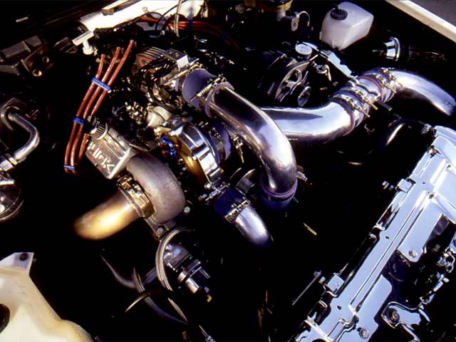
Route the 1/4" hose to the radiator and install the check valve. In the photo, the check valve can be seen next to the radiator cap. Install it so flow is allowed from the reservoir to the pump. Zip tie the 1/4" hose to the AC lines along the top of the radiator then run the line down behind the drivers side headlight area and install the fuel filter. Cut another section of hose to route to the pump.
Install the hose adapter in the pump with teflon tape and install the hose with the clamp. Note: The inlet side of the pump is the side where the red wires connect at the top.
Mount the pump using 4 1.5"L screws through the holes in the rubber pads. You'll need to drill holes in the plastic inner fender and go underneath to attach the nuts. I chose the location where the charcoal can was located from the factory.
Install the outlet hose connector and enough fuel line to reach the point on the up pipe where the nozzle will be located. Avoid routing the hose near the idler or altenator pulleys.
Remove the nut & sleeve from the end of the #3AN hose end and discard them, then twist the threaded end into the end of the 1/4" hose. An easy way to do this is with a ratchet & deep socket with a spacer inside to get the depth just right, you want the socket to grip on the 2nd hex of the AN connector while leaving the threads exposed. Once you have it, secure with a clamp. An alternate method is to purchase a braided stainless #3 AN supply line from an industrial hose store to connect the fan spray nozzle to the pump. This item should cost about \- if kept to a length of 3 feet or less.
Choose a location for the nozzle and drill a 1/4" hole in the up-pipe. Make certain that the location you chose allows for clearance between the MAF tube and the alc nozzle. Next, tap the hole with a 1/16"-27 NPT tap. 1/16" pipe taps are available through McMaster-Carr (mcmaster.com).
Mark the NOS fan spray nozzle to indicate the spray direction & wrap teflon tape on the threads then screw into the uppipe. You may want to experiment with the direction of the spray. I think it works better to spray away from the throttle body. This allows a greater distribution of the liquid into the airstream coming from the intercooler. Install the jet in the fan spray nozzle and connect the hose to it.
Wiring:
Relay pole # 85 - To pressure switch. (Other terminal on pressure switch to ground).
( If using a switch in the car, route to the switch first then to the pressure switch. )
Relay pole # 86 - To fuel pump jumper wire beneath alternator. This prevents the system from activating unless the fuel pump is running. If the pump were to activate with the engine not running, the liquid would be pumped into the intercooler and cause engine damage when the car is started.
Relay pole # 87 - To Alcohol pump (w/fused link inline).
Relay pole # 30/51 - To 12 volt post on rear of alternator (w/20Amp fuse inline).
Maintenance:
Monthly - check hoses & checkvalve for leaks.
90 Days - Remove nozzle if using the more corrosive methanol alc & check for corrosion & clogging of the jet, etc. Remove the #3AN Fem Connector from supply line & check for clogging. A stainless steel fitting is available for this location.
6 months - All of the above plus:
Inspect the inside of the up pipe. Mild steel pipes will rust. Wire brush to remove.
Remove the Fanspray nozzle and inspect it for wind erosion. The air velocity through the up pipe will wear away the nozzle which is made of aluminum. If it's thinned down in the middle, replace with a new one. Remember it's hollow so don't let it get too thin or the tip may separate and be injested by the engine. My experience is that they will last about 10,000 miles.
Another suggestion is to add a small amount of water soluable oil that's sold at fuel jobbers depots for alcohol drag racers.
Troubleshooting:
You'll either need a Mity-Vac hand operated vacuum/pressure pump or you'll need to make some test runs with the hose out of the pipe & secured inside some type of container. For just testing the pump, remove the nozzle and the #30/51 relay lead from the relay & connect to a 12V source.
Preferred Procedure:
Remove nozzle from up-pipe & start the car, with the nozzle secured in a container, apply pressure to the switch with the handpump. You can now watch the spray pattern & strength. With the test-run method you'll only be able to note the volume of fluid sprayed.
Jetting:
A .030" NOS jet works good with smaller turbos. I'd recommended that you use no smaller than a .028" jet as the smaller ones don't spray a full pattern. A .032" jet works good with a TA49.
Once the installation is complete and tested, begin increasing the boost. The amount each car will tolerate will vary depending on turbo, intercooler, timing in the chip, ambient air temperature & etc. My car usually can handle 24 psi with 93 octane without more than a degree or two of knock retard occurring and that's usually due to a slight lag in the time the car goes to 24psi & the time it takes for the alcohol to start spraying. This is mostly a situation where there isn't much load on the motor due to the low MPH where it happens and it also could be from the transmission downshifting. In the Summer, I run about about 20-21 psi and tune for even less or no knock.
Using the System:
Street use - After the car reaches normal operating temperature, find a safe area & bring the boost up to 15lbs. This will start the pump (you may feel the car become a little boggy, like it's flooding). This is normal until the boost rises or some seconds elapse & the computer starts making adjustments for the fuel change. If the car hasn't been driven in several days, this 15 psi run-up will recharge the system. Once the pump starts, it just takes a second to charge the hoses and begin spraying. Once charged, it should stay that way all day.
Track use - Race gas is my 1st choice but occaisionaly I use the in car switch and start the alcohol after going into 3rd gear.
Additional Notes:
I use the radiator overflow for the alcohol reservoir. It's capacity is 1 gal. and gives the look of an unmodified engine compartment which appeals to me. For the burp tank, I've connected an aftermarket bottle in front of the battery mounted to the core support.
You will need a Mity Vac pressure pump and an ohm meter or test light to change the pressure switch setting. Unscrew the nut while holding the stem stationary then turning the stem to change the pressure. The GM switch comes with Locktite on the adjuster screw and nut though they can be broken loose by applying some nail polish remover or lacquer thinner with a Q-Tip.
|
| |
|
|
|
|
|